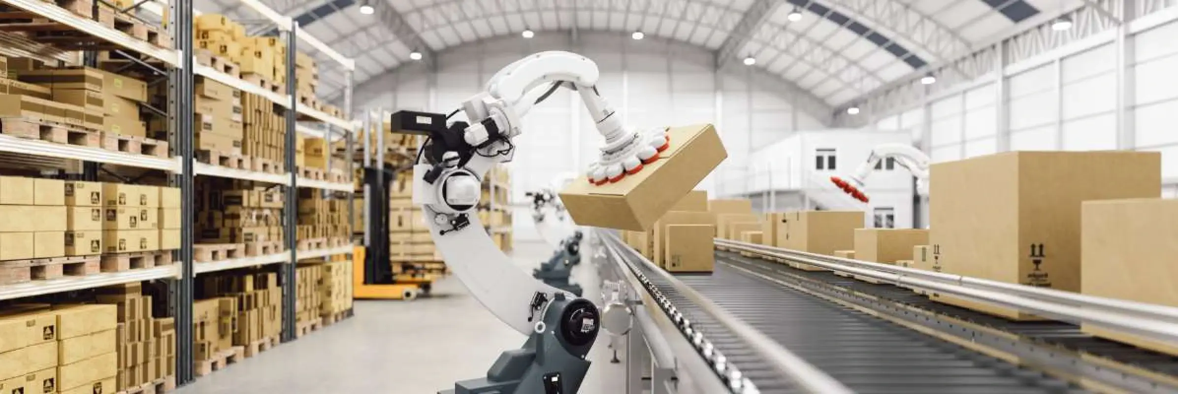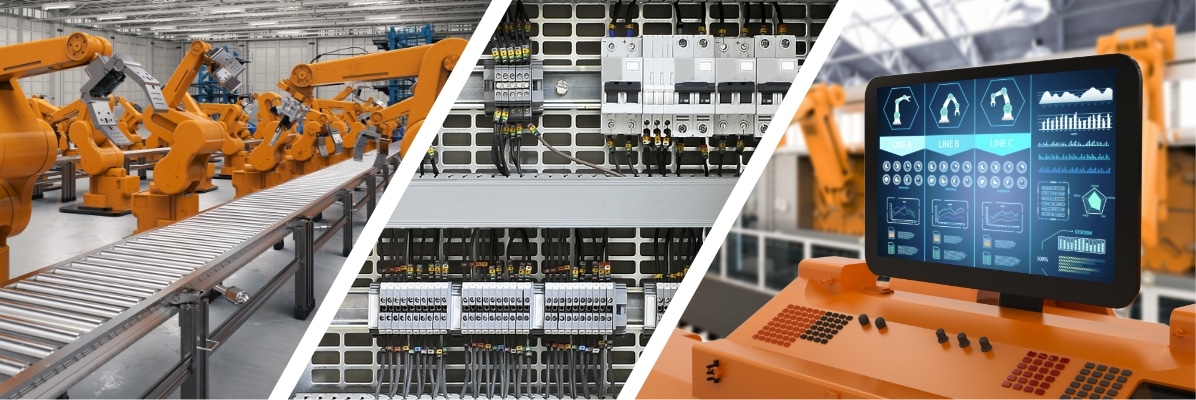

Every machine safety upgrade starts with the same uncomfortable math: a formal risk assessment has identified a guarding or control gap that must be closed, but every day that machine sits idle for modification is a day it isn’t producing. For EHS managers and controls engineers, this is the central tension of any safety retrofit. The safety obligation is nonnegotiable, yet production targets don’t pause to accommodate it.
The good news is that a well-sequenced machine safety upgrade closes the compliance gap while compressing live downtime to a fraction of what most teams expect. The difference comes down to understanding the standard, specifying the right hardware for the required Performance Level, and staging the work so the machine is only down for the final cutover.
This guide walks through the four stages of an ISO 13849-based safety retrofit, from risk assessment through validation, with the practical details a buying committee needs to scope the project accurately and a controls engineer needs to execute it.
Stage 1: Risk Assessment and Determining Your Required Performance Level
A machine safety upgrade is only as defensible as the risk assessment behind it. Under ISO 13849-1, the assessment evaluates each hazardous situation against three factors: the severity of potential injury (S), the frequency and duration of exposure to the hazard (F), and the possibility of avoiding harm once the hazard presents itself (P). The combination of these three factors determines the required Performance Level, or PLr, on a scale from PLa (the lowest) to PLe (the highest). A pinch point that an operator reaches into several times per shift carries a very different PLr than a hazard guarded behind a fixed barrier that is accessed only during scheduled maintenance.
This is where many U.S. manufacturers get confused about which rules apply. OSHA does not name ISO 13849 anywhere in its regulations. Instead, machine guarding requirements fall under OSHA 1910.212, part of Subpart O, and they are performance-based: the regulation requires that hazards be guarded but allows flexibility in the method used to achieve that protection. Because OSHA tells you what to accomplish rather than how, ISO 13849 has become the practical engineering standard manufacturers use to demonstrate that their guarding decisions are sound. Treating ISO 13849 as your design framework turns a broad OSHA machine guarding obligation into a specific, verifiable hardware specification, and it provides defensible documentation if your machine guarding OSHA compliance is ever questioned during an audit or after an incident.
The risk assessment is the foundation of the entire project. Get the PLr wrong and you either over-build at unnecessary cost or, far worse, under-build and leave a hazard inadequately controlled. South Shore Controls’ field service team conducts on-site evaluations that document existing hazards and existing control measures, giving your team the baseline needed to define each PLr accurately before any hardware is specified.
Stage 2: Selecting Retrofit Solutions to Match Your PLr
Once each hazard has a defined PLr, the next step in any machine safety modernization effort is mapping that target to the appropriate control hardware. Specifying too little leaves the gap open; specifying too much wastes capital. The mapping is reasonably well established.
For PLa and PLb requirements, the safety function can often be satisfied with mechanical interlocks or a single, simple safety relay. These are the lowest-risk situations where a single protective measure provides adequate coverage.
For PLc and PLd requirements, the architecture moves to dual-channel safety circuits with monitored feedback. This typically means redundant safety relays, light curtain systems for presence sensing, or interlock arrangements that monitor their own integrity. The redundancy ensures that the failure of any single component does not silently disable the protective function.
For PLd and PLe requirements, the standard solution is a certified safety PLC such as Rockwell’s GuardLogix or Siemens’ ET 200SP F, built on a Category 3 or Category 4 circuit architecture. These controllers run safety logic on dedicated, certified processors and provide the diagnostic coverage that the highest Performance Levels demand.
Category 3 vs. Category 4 Architecture
The distinction between Category 3 and Category 4 architecture is where many retrofit specifications go wrong, and it is worth being precise. A Category 3 architecture tolerates a single fault without losing the safety function, but if a second fault occurs before the first one is detected, the safety function can be lost. A Category 4 architecture goes further: it requires that every single fault be detected before the next demand on the safety function, so an accumulation of undetected faults cannot defeat the protection. PLe almost always requires Category 4. Specifying the right category is not a matter of preference; it is dictated by the PLr your risk assessment produced.
This stage is fundamentally a control engineering exercise. South Shore Controls designs and builds the dual-channel safety circuits, relay panels, and safety PLC programs that these specifications require through its system integration services and pre-builds the necessary control hardware in-house through its Electrical Panel Division.
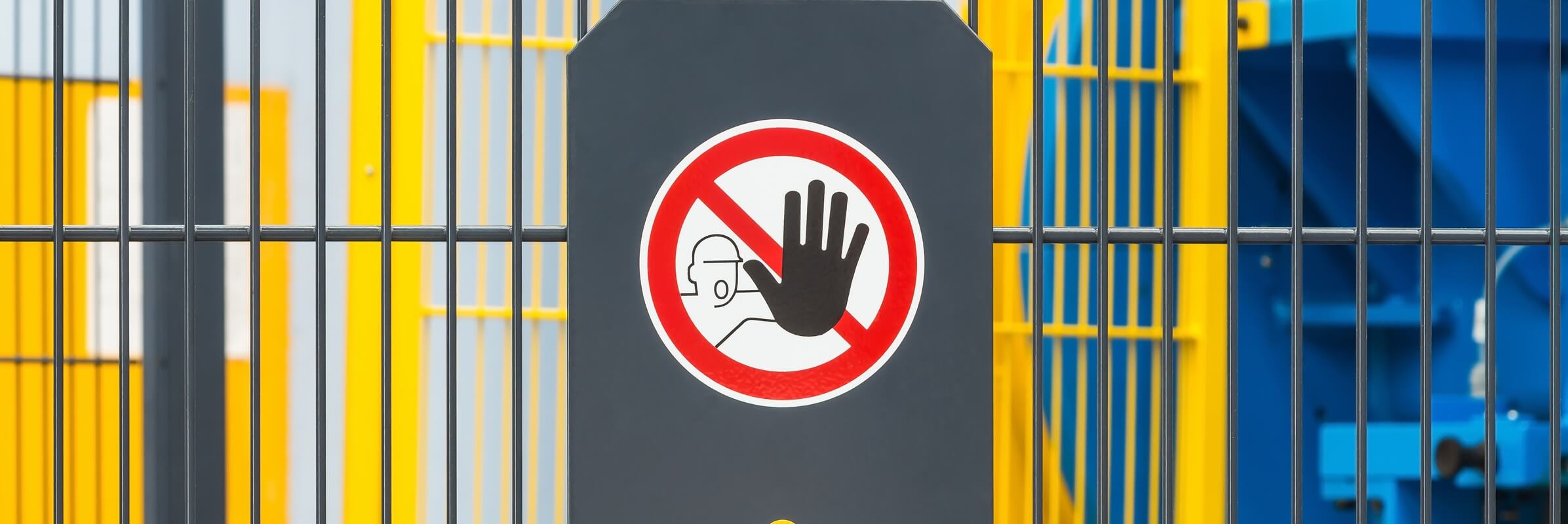
Stage 3: Integration Without a Full Shutdown
The hardware specification is settled. Now comes the question that keeps plant managers awake: how long is the machine down? The answer depends almost entirely on how much of the work is done before anyone touches the live machine.
The most effective strategy for safety system integration is to move as much labor as possible offline. Wiring preparation, harness fabrication, and the assembly of the safety relay panel can all happen at the integrator’s facility while the machine continues to produce. Pre-built safety panels arrive ready to mount and terminate, turning what would be days of in-place wiring into hours.
Safety PLC logic can be written and validated against software simulation well ahead of the installation date, so the program that loads onto the machine has already been exercised against the expected I/O. By the time the line goes down, the only work remaining is the physical cutover: mounting the panel, landing the field connections, and commissioning. This is what compresses live downtime from a week to a long weekend or a single planned maintenance window.
One step in this stage is mandatory rather than optional. Whenever you modify control circuitry, OSHA 1910.147 lockout/tagout procedures must be followed during the work, and the LOTO procedure must be updated to reflect the new control scheme. A safety retrofit that changes how a machine is de-energized but leaves the old LOTO documentation in place has created a new hazard while closing another. This is a compliance requirement, not a best practice.
South Shore Controls builds its turnkey solutions services around exactly this staged model, combining in-house design, panel fabrication, and testing and validation before equipment ever reaches your floor. For retrofits to existing equipment and enclosures, the on-site retrofits team handles the live-machine work, and on-site commissioning brings the upgraded safety system into service with the shortest possible production interruption.
Stage 4: Validation and Verifying the Achieved Performance Level
Installing the hardware does not complete a machine safety upgrade. ISO 13849 requires that you verify the Performance Level the system achieves and confirm that it meets or exceeds the PLr required by the risk assessment. Validation rests on three pillars.
The first is architectural verification: confirming that the circuit was wired to the category the design called for, with the redundancy, separation, and monitored feedback that Category 3 or Category 4 requires is present in the installed system.
The second is the component MTTFd calculation, which uses the mean-time-to-dangerous-failure data published by each component manufacturer to confirm that the assembled chain of devices achieves the reliability the target Performance Level demands.
The third is functional safety testing: physically exercising each safety function, including fault conditions, to confirm the system responds exactly as designed when a guard is opened, a light curtain is broken, or a fault is introduced.
Only when all three line up, the architecture is correct, the calculated reliability is sufficient, and the functional tests pass, can you document that the achieved PL meets the required PL. That documentation is what closes the loop on the original risk assessment and demonstrates that the gap has been verifiably eliminated. South Shore Controls treats testing and validation as a defined project deliverable, producing the verification records that make your compliance defensible.
Why Manufacturers Choose South Shore Controls for Safety Retrofits
A machine safety upgrade sits at the intersection of regulatory compliance and controls engineering, and most vendors are fluent in only one of those languages. South Shore Controls understands the OSHA standard, the ISO 13849 framework behind the specification, and the hardware implementation required to satisfy it.
From in-house design and panel fabrication that enable work to be done offline, through system integration and final commissioning, the entire retrofit is handled under one roof at the company’s facility in Mentor, Ohio. That single-source model is also what keeps these projects fast, because the same team that engineers the safety circuit builds the panel and commissions it on your floor. Explore the full range of automation and control solutions to see how a safety retrofit fits within a broader modernization strategy.
FAQs
Who is legally qualified to perform the risk assessment that determines our PLr requirements?
There is no single license or certification that OSHA mandates for the person conducting a machine risk assessment. What matters is competency: The assessment should be performed by someone with documented knowledge of the machinery, the hazards involved, and the applicable standards such as ISO 13849-1 and ANSI B11. In practice, this is often a qualified safety engineer, a controls engineer with functional safety training, or a third-party integrator working alongside your EHS team. The key is that the assessor’s qualifications and the assessment methodology are documented, because that documentation is what makes the resulting PLr defensible. South Shore Controls’ field service team works with plant EHS staff to produce this documented baseline.
If we add a safety PLC to an existing machine that already has a standard PLC, do we need two separate processors?
Not necessarily, but you do need separation between standard control logic and safety logic. A certified safety PLC such as GuardLogix runs safety-rated logic on a dedicated, certified safety processor while still handling standard control tasks, so a single controller can manage both as long as the safety functions execute on the certified safety portion. In many retrofits, the existing standard PLC remains in place to run the machine’s normal sequence, while a safety controller is added to handle only safety functions. The right approach depends on the age and architecture of the existing controls, which should be evaluated during the design phase of the system upgrade.
What is SISTEMA, and is it required to validate our ISO 13849 compliance?
SISTEMA is a free software tool published by the German institute IFA that automates Performance Level calculations in ISO 13849-1, including MTTFd, diagnostic coverage, and the resulting PL for a given safety function. It is widely used and makes the verification math far easier, but it is not legally required. ISO 13849 requires that the achieved Performance Level be verified; it does not mandate a specific tool for verification. You can perform the calculations manually or with another validated method. That said, using SISTEMA produces clean, reproducible documentation that holds up well in an audit, which is why many integrators rely on it as part of their testing and validation process.
Let’s Close Your Safety Gap
If a risk assessment has identified a guarding or control gap on your equipment, the path from finding to fixing doesn’t have to mean extended downtime. South Shore Controls partners with EHS and engineering teams to scope, specify, build, and validate machine safety upgrades that meet your required Performance Levels and respect your production schedule.
Contact our engineering team today to schedule a consultation and start scoping your safety retrofit.